O-rings may be used in static or dynamic applications. Static applications, e.g. flange seals, lid seals, manhole seals, etc., are defined as applications where the parts to be sealed do not move relative to each other. A dynamic application is defined as an application where the sealed surfaces move relative to each other.
The various designs can be defined to the type of seal as follows:
O-rings are particularly suitable for use in static applications because the applied deformation produces a sealing effect which increases with increasing system pressure. A correctly designed gland with the appropriately sized seal is important, but not alone responsible for an effective seal. The compound used influences the sealing function. In all applications, it is correct to select an O-ring with the largest possible cross-section allowed by the design constraints. In general, it can be said that an O-ring circumference should not be stretched more than 6% nor compressed more than 1 to 3% in assembled condition. The hardness of an O-ring is selected to the applied pressure, the tolerances are given and the surface finish of the elements to be sealed.The elongation or breathing of metallic materials (e.g. lids, flanges, cylinder walls) under pressure must be considered. Due to this so-called “breathing”, an oversized clearance gap can occur. This results in a gap which the O-ring must bridge. The economics of production is often a reason why large tolerances are worked to and resulting in larger clearance gaps. A Parker PARBAK® back-up ring can be used to bridge an oversized gap. The PARBAK® protects the O-ring because of its concave face and stops extrusion. PARBAK® back-up Ring Size List 5701 E gives all back-up rings suiting O-ring sizes 2-001 to 2-475 (more information see Section 8). For silicone and fluorosilicone compounds, the allowable gap size is 50% of that normally allowed with other compounds. These materials have very poor extrusion and tear resistance properties. High pulsating pressure and relative movement of machine parts are the causes of war. Additionally, a pulsating pressure causes breathing or flexing of components which also results in a larger gap. If signs of wear are found on a static seal, the gland surface finish shall be improved or an O-ring made from the polyurethane Parker Hannifin compound (ULTRATHAN®) shall be fitted.
.png)
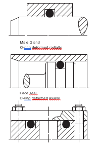
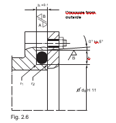
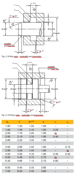
The O-ring is deformed in an axial direction. Under pressure, the O- the ring is subject to a relative movement. It is important to consider the pressure direction.
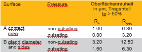
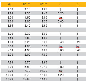
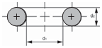
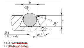
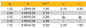
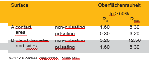
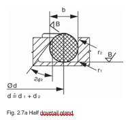
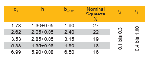
The dovetail groove shape is used where it is necessary to keep an O-ring in its position, e.g. during surface work, on opening and closing of tooling where otherwise the O-ring would drop out of the gland. Machining of the gland is difficult and expensive.
Where a pulsating pressure exists, O-rings for thread M 22 x 1.5 and larger should be produced in extrusion resistant polyurethane P5008. Under such conditions, O-rings in NBR are not suitable.
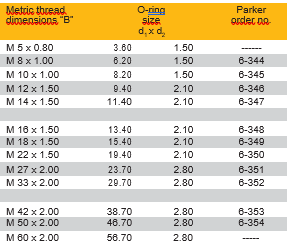
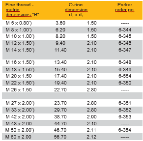
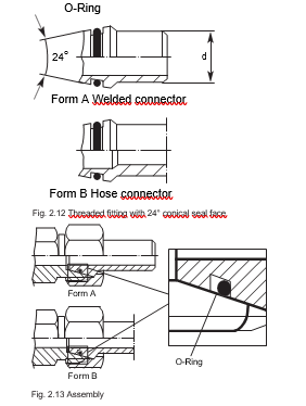
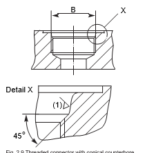
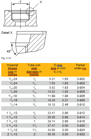
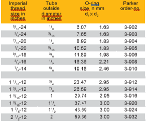
2.3.4 Threaded connectors SAE J 514, Table 14, and MS 16142 straight threaded bore.

The number of parameters affecting dynamic or reciprocating seals is far greater than those on static seals. Oscillating and rotating seals also are considered to be dynamic. O-rings have proven suitable in all these applications. To reduce friction and wear, dynamic O-rings are deformed less than static O-rings. O-rings in hydraulic and pneumatic applications are assembled in the gland. O-rings are used best for short strokes and small diameters. O-rings in long stroke applications with relatively large diameters can be used successfully if correctly fitted. It is necessary to consider all factors which influence the sealing function and take the appropriate measures in the design stage. The compound hardness is selected according to the applied pressure. The most usual O-ring hardness is between 70° and 80° Shore A. Should the danger of extrusion exist (e.g. where dynamic seals are subject to high pressure) two back-up rings should be fitted. In new designs the following factors should be considered:
e.g. extreme temperatures
Reciprocating type seals and their gland design can be subdivided into hydraulic and pneumatic applications.
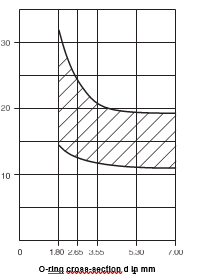
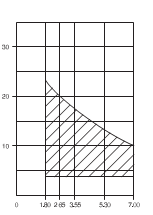
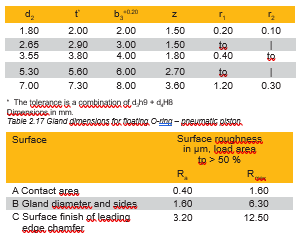
O-rings are used in piston and piston rod seals. They provide good results over a wide range of pressures and sometimes also are used with back-up rings. The average deformation of the cross-section is between 10% and 15% (see Fig. 2.17). The minimum deformation of 8% should not be exceeded when all tolerances are considered. 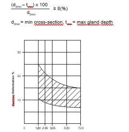
The O-ring, when used as a piston seal, can be compressed by 1 to 3% of their circumference. The amount of force required to compress the circumference depends on the O-ring inner diameter and decreases with increasing inner diameter. O-rings may be stretched by up to 6% when assembled in piston groove. Compounds featuring highest wear resistance should be selected. The compound should not shrink in the medium nor be subject to high swell which increases friction and reduces extrusion resistance. Normally, a compound hardness from 70° to 80° Shore A is recommended. In this range, a compromise between friction and wear is attained. Softer O-rings have a higher wear rate, harder O-rings feature higher friction at pressures of 150 bar. At high pressures, there is the risk of extrusion. With large gaps and higher temperatures, back-up rings should be used.
The interest in pneumatic systems has increased over the past few years. Pneumatic systems offer certain advantages over hydraulic systems, e.g:
The average deformation of the O-ring cross-section is reduced in comparison with hydraulic applications and the resulting wear is at the minimum possible level.
The average deformation of the O-ring cross-section is reduced in comparison with hydraulic applications and the resulting wear is at the minimum possible level. Minimum deformation of the O-ring cross-section normally is between 4% and 7% and includes all tolerances.
.png)
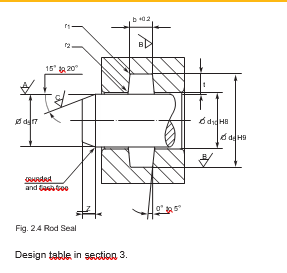
O-rings in rod seals admit compression by 1% to 3% of their circumference. In piston seals, they admit elongation by 6% of their inner diameter. In addition to standard materials, a wide range of special compounds with improved friction capability are available. These compounds can be discussed with our Applications Department. A compound hardness between 70° and 80° Shore A is recommended.
Pneumatic pistons mostly are assembled with floating O-rings. The cross-section is not deformed. This reduces friction. In this way, the piston moves extremely easily and the O-ring is not subject to wear. The outside diameter of the O-ring is a little larger than the cylinder inside diameter to ensure the seal function. The inside diameter d1 should not contact the groove inside diameter. The gland depth must be larger than the O-ring cross-section. On pressurizing, a certain amount of leakage occurs until the O-ring is in contact with the surface to be sealed. A compound hardness between 70 and 80 Shore A is recommended. Standard compounds are used in the pressure range up to 16 bar and with temperatures up to 80°C. Contact us for assistance in selecting wear resistance and specially treated O-rings.
O-rings can be used as low power transmission elements They are not only an economic solution but also offer many advan- tages:
An O-ring compound is selected for minimum stretch relaxation (tensile set) and maximum dynamic properties. The choice of elastomer is made to the environment:
The general requirements are:
EPDM is not resistant to mineral oil and grease.If the contact with lubricant from bearing housing or machine parts could not be avoided, silicone oil and grease should be used. C 557-70, Chloroprene Rubber, CR. Temperature resistant up to appr +80°C. CR is compatible with mineral oil and grease, but the dynamic properties are not as good as those of EPDM and PUR. The stress relaxation of CR is as good as that of EPDM. S 604-70, Silicone Rubber, VMQ. Temperature resistant to approx. +100°C (maximum to +150°C). VMQ is normally used where high temperatures apply. The ten- sile strength and wear resistance are poor compared to other compounds.
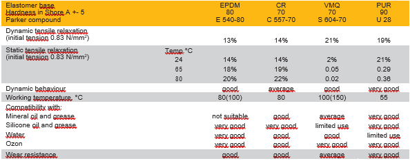
P5008, Polyurethane Rubber, PUR Temperature resistant up to appr +55 °C (dependent on relative humidity). PUR is noted for its higher mechanical properties, wear resist- ance and lifetime. Because of this, the application of PUR under hardest working conditions is possible and larger loads can be transmitted. The following table 2.19 compares drive belt elas- tomers according to their properties using values obtained from tests with the O-ring size 2-153, 88.6 x 2.6 mm.
Compounds for drive belts
The following compounds have proven themselves under the above conditions. E 540-80, ethylene propylene diene Rubber, EPDM. Temperature resistant up to +80°C (max +100°C). EPDM is not resistant to mineral oil and grease.If the contact with lubricant from bearing housing or machine parts could not be avoided, silicone oil and grease should be used. C 557-70, Chloroprene Rubber, CR. Temperature resistant up to appr +80°C. CR is compatible with mineral oil and grease, but the dynamic properties are not as good as those of EPDM and PUR. The stress relaxation of CR is as good as that of EPDM.
S 604-70, Silicone Rubber, VMQ. Temperature resistant to approx. +100°C (maximum to +150°C). VMQ is normally used where high temperatures apply. The ten- sile strength and wear resistance are poor compared to other compounds.
P5008, Polyurethane Rubber, PUR Temperature resistant up to appr +55 °C (dependent on relative humidity). PUR is noted for its higher mechanical properties, wear resist- ance and lifetime. Because of this, the application of PUR under hardest working conditions is possible and larger loads can be transmitted. The following table 2.19 compares drive belt elas- tomers according to their properties using values obtained from tests with the O-ring size 2-153, 88.6 x 2.6 mm.
Dynamic tensile relaxation:
testing period: 72 h
testing temperature: room temperature
drive pulley: 15.5 mm dia
speed: 1740 R.M.P
tension: 0.83 N/mm2
Loading: Momentum of the driven pulley (cast iron) 66.5 mm dia in a test cycle taking 3 minutes with 15 seconds to stand still.
Static tensile relaxation:
testing period: 48 h
pre-tensioning: 0.83 N/mm2 between two pulleys with 12.5 mm dia.
temperature: see table
Design information
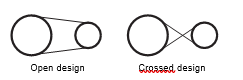
Ordering detail All O-rings which are used as drive belts are subject to additional quality inspection procedures and inspection for surface defects under elongation. O-rings ordered for this application are to be coded as follows: “2-250 E 540-80 – Drive Belt” Calculation fo a drive belt open design.
Abbreviations:
A. Center line distance of pulleys (mm) D1 Diameter of driven pulley (mm)
D2. Diameter of drive pulley (mm)
S. Elongation as a decimal (e.g. 10 % = 0.1) d1 O-ring inner diameter (mm)
d2. O-ring cross-section (mm)
L. Length of drive belt (mm)
B. Calculation factor
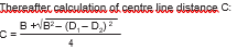
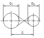
Crossed design
Abbreviations:
C Center line distance of pulleys (mm) D1 Diameter of driven pulley (mm)
D2 Diameter of drive pulley (mm)
S Elongation as a decimal (e.g. 10 % = 0.1) d1 O-ring inner diameter (mm)
d2 O-ring cross-section (mm)
L Length of drive belt (mm) B Calculation factor
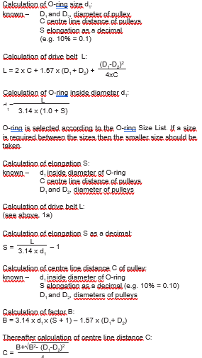
Calculation of O-ring size d1: known –
D1 and D2, diameter of pulley
C centre line distance of pulleys
S elongation as a decimal (e.g. 10% = 0.1)
Calculation of drive belt L.
L = 2 x C + 1.57 x (D + D ) + (D1-D2) 21 2 4xC Calculation of O-ring inside diameter d1:
d = L
1 3.14 x (1.0 + S)
O-ring is selected according to the O-ring Size List. If a size is required between the sizes then the smaller size should be taken. Calculation of elongation S:
known – d1 inside diameter of O-ring
C centre line distance of pulleys
D1 and D2, diameter of pulleys