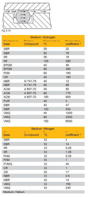
The number and variety of criteria which affect a sealing element often are underestimated by users. The chemical properties of a medium and the physical working conditions are singularly important when selecting an elastomer and designing a gland. The Medium Compatibility Table, (catalogue no. 5703 E), indicates the rating of each elastomer and finally recommends the most suitable compound. This section describes the terms most often used in the sealing industry. With the knowledge of this general terminology, an engineer can quickly select the correct compound to seal a given medium.
Wear can be quantified in the laboratory with tests carried out according to DIN 53 516. The tests which involve pressing a test sample against a rotating abrasive cloth are a suitable means to compare elastomers. Wear resulting from normal working conditions cannot be related to laboratory tests because practical tests are carried out under constantly changing conditions. Practical tests give reliable figures as a result of numerous influences which cannot be simulated in a laboratory.
HNBR, NBR, EPDM, CR and FKM have good wear resistance properties. Silicone and fluorosilicone have poor wear resistance.
Ageing can be measured as a loss of physical properties and depends on the type of caoutchouc molecule chain. The long molecular chain includes many smaller side chains. This com- binations are prone to be affected firstly by chemical reactions. There are three characteristic types of reaction which cause ageing:
Ageing tests are carried out under simulated working conditions, e.g. in a heated oven. Ageing of elastomeric materials is accelerated at elevated temperatures. Tests are made in compliance with DIN 53 508 and subject to temperature and time chose to the elastomer type and working conditions. e.g.
The physical properties are measured before and after ageing: hardness, tensile strength, elongation at break and tensile stress (modulus) A minimum change indicate better resistance to ageing.
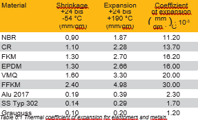
According to the recipe, elastomers show a coefficient of a thermal expansion near a factor 10 times greater than that of steel. It is therefore important in borderline cases to know how much a seal shrinks in cold condition or expands at high temperatures and how this affects the elastic force on the seal face. At low temperatures, a reduced elastic force on the seal face can lead to leakage when additional shrinkage occurs. In dynamic applications, the additional heat generated due to friction can lead to increased force as the seal expands (provide for sufficient material as a heat sink!).
Whenever high-performance elastomers such as FFKM are used at temperatures above 200°C, special attention must be paid to thermal expansion when designing the groove. The temperature rises to 300°C may result in the volumetric expansion of up to 30 %. If the seal is unable to perform this thermal expansion, this leads to high levels of stress that may damage seals and mating components.
Compression set is the term which describes an elastomer's loss of elastic memory. The compression set test is carried out on a standard test sample or an O-ring at high temperature under a deforming load and measured at room temperature after relieving the load. In general, it can be said that the better the elastomeric memory the lower the compression set. The compression set is measured as a percentage of the original deformation of the O-ring cross-section or button height. The compression set depends on the elastomer base, recipe, manufacturing conditions, testing temperature and time, deformation of the specimen, on the thickness of the specimen and the contact medium Tests are made to DIN ISO 815 or ASTM D 395 Method B with deformation of 25 % in a circulation hot air oven. An additional test in the medium (oil, steam, etc.) gives values for swelling, shrinkage etc. which would occur in practice. The cold flexibility and the elastic condition at freezing temperatures also can be quantified by the above test. The specimen is deformed and frozen; the “set” is measured before temperature rise after relief of the specimen from the bench.
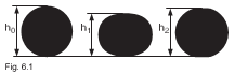

h0 = O-ring cross-section or original height of the specimen h1 = height of deformed specimen
h2 = height of relieved specimen (after a defined time delay)
The test result depends on the O-ring cross-section. Figs 6.2 and
6.3 show the deformation.
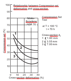
It can be seen that the compression set of NBR compounds is in- fluenced by the cross-section of the specimen to a higher degree than with VMQ (Silicone) compounds (see Figs 6.2. and 6.3). The compression set is minimum at 25 % to 30 % deformation.
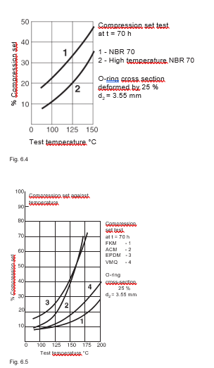
The influence of temperature on the test results depends on the base elastomer and its ability to withstand high temperatures. The trend to accelerated ageing and the loss of original physical properties increases at high temperatures (and with longer time).
Fig 6.4. shows the increased temperature resistance of high temperature NBR 70 as improved (lower) compression set results. Fig. 6.5 illustrates a comparison of various elastomers. FKM and VMQ show significantly lower compression set results, also at +200°C. The medium contacting the elastomers should not be neglected. EPDM is compatible with air up to +150 °C. In a medium such as steam (absolutely compatible with EPDM), the compression set would be much less. The reverse is true with FKM and VMQ, a much worse result would be expected in steam. Fig. 6.2 to Fig. 6.5 show compression set tests carried out through a period of 70 hours. Shorter tests, e.g. over 22 hours, give better results; longer tests, e.g. over 168 hours, give worse results. Results of compression set tests can be compared only when all factors affecting the test results are relative, e.g. test method, specimen, geometry, deformation, testing time and temperature, and the contact medium. To some extent the results of measurements allow conclusions to be drawn concerning the seal’s behaviour in the particular application. Yet without knowledge of the exact application conditions it is impossible to evaluate the effects of compression set in the application. For example, seals with 90 % compression set may retain their sealing performance, whereas under certain operating conditions a compression set of merely 60 % may lead to seal failure.
O-rings as sealing elements are described in DIN 3770 (now replaced by DIN 3771) as follows:
The effect of a medium on an elastomer ranges from slight shrinkage to heavy swelling. However, such changes are not limited only to a change in volume, they can bear considerable effect on hardness, tensile strength and elongation which can be an additional cause of leakage. The effect of a medium always will be accelerated at higher temperatures. With mineral oil as medium, the changes in physical properties are the result of two processes: Oil diffuses into the rubber causing swelling which is limited and differs from one elastomer to another. Parts of the elastomer can be dissolved or extracted from the compound resulting in shrinkage. The processes can be concurrent and the resulting volume change may not be noticeable.
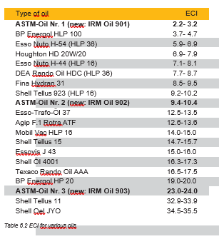
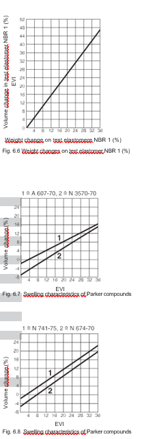
The effect does not only depend on the construction of the elastomer but also the hydraulic fluid. The base elastomer contains between 15 % and 50 % acryl-nitrile (ACN). The higher the ACN content, the better the compatibility with oil. In the same way, high content of aromatics (e.g. as in paraffin based oils) leads to a low tendency to swell (also with low ACN content). Conversely, naphthene based oils cause swelling which for some elastomers does not tend to reach equilibrium, e.g. with NBR. A high ACN content is necessary to resist swelling resulting from naphthene based oils. To select the correct compound without carrying out extensive laboratory tests we have developed a simple reference test called ECI (elastomer compatibility index). Countless tests have proved that there is a linear relationship between the ECI and the volume change of elastomers based on NBR, ACM, FKM and CR rubbers. By using the ECI, the volume change of the above elastomers can be predicted in a mineral oil thus saving valuable laboratory time. The ECI for oil is initially determined in the laboratory (see also Table 6.2). The ECI values can be plotted on a compound specific graph (Figs 6.7. and 6.8) and the expected volume change can be read directly from the vertical axis. In this way, a decision can be taken regarding elastomer compatibility with oils. Our procedure now has been standardized under international standard ISO 6072. On request, we are pleased to test any oil to determine its ECI. However, anybody can test for the ECI as follows: The weight change of a test elastomer, e.g. NBR 1 to ISO 6072, is measured after immersion in the respective oil for 168 hours at +100 °C. The ECI then is simply read from Fig 6.6 plotting the weight change.
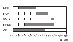
Electrical properties of elastomers According to type, elastomers are good insulators, semiconductors or conductors. The type of rubber and filler (electrically conductive carbon black) can be selected to meet electrical requirements.
Criteria:
Most elastomers are required to be conductive to avoid electrostatic charging, e.g. fuel tank seals, drive belts, medical equipment, etc. When special compounds are required, care should be taken to ensure that conductive parts of the compound recipe are not dissolved or extracted by the medium being sealed, thereby changing the electrical properties.
Sometimes metal surfaces in contact with elastomers show signs of corrosion. This takes the form of chemical attack upon a metal surface. The various types of corrosion have definite characteristics and can be described as general corrosion, pitting gap corrosion, and intercrystalline corrosion. The presence of corrosion where metals and elastomers are in contact may have different causes:
Rubber compounds often are vulcanised using an accelerator containing the element sulphur. A large percentage of the sulphur under the influence of heat (vulcanisation) forms bridges (cross-links) among the elastomer molecule chains. This sulphur remains chemically fixed and cannot be extracted. On the contrary a smaller portion of sulphur remains free and not fixed in the elastomer structure.
Free sulphur in contact with many metals and alloys (e.g. silver, copper, lead) tends to form metal sulphides which cause discolouring and corrosion damage. Further, a reaction between metal and sulphur can lead to the failure of a dynamic seal if rubber sticks to the metal surface after a long down-time. To avoid machine breakdown caused in this way, use of a sulphur-free compound is recommended.
Hydrochloric acid can be formed in certain environmental conditions when free chloride is present in an elastomer. Compounds in CR, ECO, CO and to a lesser extent in ACM tend to cause corrosion if the recipe does not contain sufficient amounts of inhibitors and stabilizers (e.g. metal oxides) which retard free chloride. Hydrochloric acid also can be formed around compounds which are free from chloride (e.g. SBR and NR) if they contain chloroparaffin combinations which are used as flame retardants.
The formation of small galvanic cells is the main mechanism responsible for corrosion of metals. A galvanic cell is formed across two dissimilar metals. An electrolyte is required for the function of a galvanic cell. Alloys made up from different metal phases or crystals can be damaged when small local cells are formed. Electro-Chemical corrosion in the region of a seal element (e.g. an O-ring) does not necessarily mean that always the elastomer is the cause. It is very difficult to say how much electrochemical corrosion depends on the elastomer. It is assumed that condensate accumulates between the rubber and the metal which together with other impurities causes electrochemical corrosion. The trend to corrode depends on the type of metal alloy, surface roughness, state of the metal, temperature and humidity.
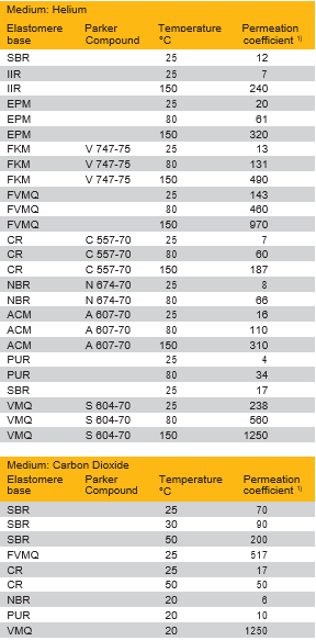
All elastomers allow gas to enter their structures, to permeate through and leave at the low-pressure side. The rate of permeability through an elastomer depends on the type of gas, elastomer base, temperature and pressure difference. The permeability rate is of great importance in the vacuum and gas industries (see Section 7.12). Calculation of the rate of gas permeation The rate of gas leakage through an O-ring can be calculated as an approximation when the elastomer permeation rate and the working temperature are known. Table 6.4 gives various gases with their gas permeability coefficients. The following formula can be used to calculate an approximation:
L [ 0,4 · F · d1 · P · Q (1-S)2
where:
Assumptions:
The term hardness is the measure of the resilience of materials to a deforming force of a harder element of defined shape in a given period. Hardness is measured in units of Shore or IRHD (International Rubber Hardness Degrees). The hardness of specimens normally is compared using a hardness testing machine graduated in degrees Shore A. The hardness of fin- ished components normally is measured in units-degrees IRHD. Measurement of hardness on finished components gives different results to measurements on specimens because finished components have various thicknesses and surfaces are not flat.
Tests of hardness are carried out to:
Softer O-ring material settles easier into the microfine imperfec- tions in the surface to be sealed than harder material. This is ad- vantageous where system pressure is low; normally high system pressure would cause this effect with a harder O-ring. The rule is: low pressure – softer O-ring.
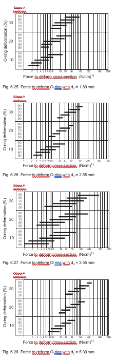
In sensitive applications where the force required to deform the O-ring is critical, please consult Tables 6.25 to 6.29 in capitel
6.22. The force required to deform an O-ring of a given hardness by a given percentage can be taken from the tables. This can be critical because fitting becomes increasingly difficult when the forces required to deform a large O-ring are high. Where a housing is made from inherently weak material, e.g. plastic or aluminium, the O-ring can damage the housing when the forces needed to deform the O-ring exceed the strength of the housing material. In dynamic applications the hardness of the O-ring is even more important.
Generally it is true to say that for the same gland dimensions that a harder O-ring shows higher stick-slip effect. Conversely, the harder compound has a lower coefficient of friction.
Harder compounds have a higher resistance to extrusion. In high pressure systems hard O-rings are used as flange seals; soft O-rings with a hard Parbak® back-up ring are used in piston and piston rod seals to prevent extrusion.
If a freely suspended rubber strip is loaded and stretched and subsequently heated, the strip will contract and lift the load. Conversely, an unloaded strip when heated expands to the coefficient of expansion for that rubber. This phenomenon of contraction is termed Joule effect and occurs only when heating a stretched rubber object.
Example: O-ring as radial shaft seal. The O-ring with an inner diameter smaller than the shaft is fitted under tension. The O-ring heats up due to friction and contracts. The result is increased friction and temperature. Failure of the O-ring is characterised by a hard and brittle O-ring surface.
In practice an O-ring of larger inner diameter must be selected. An inner diameter between 1% to 3% larger than the shaft is recommended and the outer diameter of the gland should ensure that the O-ring is compressed on the shaft surface. The width of the gland should be slightly less than the cross-section diameter. The O-ring always should be fitted into the bore and never on to the shaft.
Properly stored rubber products can retain their properties for many years without any appreciable changes. Unfavour- able storage conditions, however, will quickly make seals unusable.
Storage conditions
Standard conditions for storage, cleaning, and maintenance of rubber products have been defined by DIN 7716 and ISO 2230. The following is an extract listing the critical conditions to be met by storage facilities:
Storage time A crucial element determining the storage period of elastomers is the time of vulcanisation. Parker marks packing bags with the re- spective manufacturing date. “1Q03”, for example, means parts produced in the First quarter of 2003. As a general rule, prior to installation, all elastomer products should be checked to confirm that they are in proper condition. Negative changes caused by inappropriate storage can usually be detected by visual inspections. These involve the following key characteristics: contamination, cracking, hardening, soften- ing, stickiness and discolouration. For critical or safety-relevant applications, it is recommended to follow DIN 9088, Aerospace, which limits the recommended storage period to 40 quarters. This period may be extended after inspecting the parts for the above-mentioned characteristics. Parker Seal Group labs offer these inspections as a service to users. The storage period ends when the components are installed.
Cleaning Rubber products should be cleaned, using a clean cloth and tepid water. Petrol, benzene, turpentine, etc. are not suitable. Sharp-edged or pointed objects, such as wire brushes, grinding paper, etc. must not be used on the products. Drying of rubber products near radiators/heaters is not recommended.
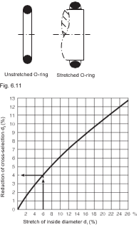
When an O-ring is stretched its cross-section becomes oval. In critical sealing applications this change in cross-section can lead to leakage. The reduction in cross-section reduces deformation and therefore the sealing capability in assembled parts. The ovality of cross-section can be allowed for in the design stage modifying the gland depth accordingly.
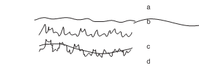
The lifetime of a seal is influenced directly by the quality of the surface over which it moves and by the groove finish. Rough- ness of the surfaces varies to the type of application, static or dynamic. Section 2 gives detailed information about the different applications and the recommended maximum surface rough- ness. Perfect surface finish cannot be achieved. The roughness of a surface as measured comprises several elements which can be handled separately to DIN 4760:
All these deviations from the ideal finish are superimposed as measurement is carried out and represent the surface (see Fig 6.13, surface finish structure).
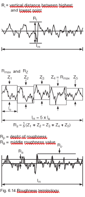
Surface finish often is quantified in terms of Rt and Ra (see Fig.
Roughness terminology). Rt is the vertical distance be- tween the highest and the lowest peaks in a roughness profile over a test length lm. Rt is increasing, being replaced by Rmax, the maximum depth of roughness. Rmax is the greatest single roughness found in 5 consecutive single trace lengths le. This is given in Fig 6.14 by the roughest profile Z4. In this case Z4 = Rmax does not include extreme roughness peaks as is the case of Rt.
The middle roughness value Ra is an arithmetic mean of all components of the roughness trace within the trace length lm. Rz, he average roughness value of 5 consecutive trace lengths le is often preferred to Ra. If Ra is known, Rz can be taken from Fig 6.15 and vice versa. Fig is taken from DIN 4768, part 1, attachment 1. Should Rz reach the upper portion of the graph it can be assumed that the specified Ra values will not be exceeded. The lower limits would Finally, the depth of roughness Rp also is of interest and is the vertical distance between the highest point on the roughness trace and the center line of that tracebe taken if a Rz value should be specified.
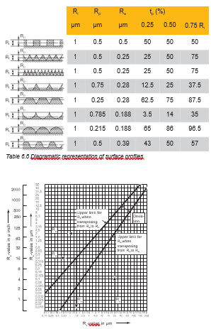
Values for Rt are of very little assistance in reaching a conclu- sion regarding the suitability of a surface roughness from the sealing point of view. Table 6.6 shows that for a similar Rt all levels of roughness can be produced. Ra values are unsuit- able for comparison because profiles 6 and 7 have the same Ra value. Rp values without reference to the load area tp also gives a false impression of roughness. A static sealing surface Rt ≤6.3 µm (old: QQQ roughness DIN 3141; new: ÖRt6,3 roughness DIN IS0 1302) is rougher than the dynamic surface requirements. Seal manufacturers recommend a roughness Rt ≤ 2.5 µm for a dynamic sealing surface (Ra = 0.25 to 0.5 µm ) (old: QQQ rough- ness DIN 3141; new: ÖRt2,5 roughness DIN ISO 1302) when the load area is over 50%, or when the surface finish roughness Rp is under 50%. These limitations often are overlooked, neverthe- less the connection between surface finish and load area is very important because an “open” profile can have sharp edges (e.g. profiles 2 to 6 in Table 6.6). These open profiles are a product of cutting processes such as turning or grinding. A much larger load area is produced by cold forming processes such as rolling, drawing or sinking.
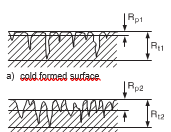
It can be clearly seen from Fig 6.16 that surfaces produced by roller burnishing have no sharp peaks which can cause damage to a seal. Further, the valleys form potential lubrication reservoirs which improve the dynamic behaviour of a seal.
Surface finish values obtained in a single test are possibly not typical. For this reason several readings should be taken. When several results are to be compared, the length of the test surface must be stated – for different trace lengths results are not compa- rable because they result from other profile heights.
O-rings load a sealing surface due to their own resilience com- pounded with any system pressure. When the surface to be sealed moves relative to the O-ring, frictional forces are set up producing two effects: one leads to wear and the other reduces the useful load which a cylinder can transmit.
In dynamic applications a difference must be made between break-out and running friction. Break-out friction must be over- come at the beginning of movement and is also known as start- up friction. Once movement is established the frictional forces drop to a lower level and sliding begins. This can clearly be seen in reciprocating cylinders The running friction of seals depends on countless factors mak- ing a mathematical analysis practically impossible. For this rea- son it is difficult to make exact statements regarding the level of friction which can be expected. The most important factors are:
Related to the seal:
Related to the hydraulic fluid:
Related to the working conditions:
These factors cannot be quantified because they overlap and act cumulatively.
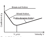
At the beginning of a stroke the seal goes through 3 friction phases. Initially the seal is in direct contact with the sealing face with few lubricated fields, i.e. µ=0.3. It then follows a wider area of mixed friction where the coefficient of friction can drop as low as 0.06 to 0.08 according to the proportion of lubrication / non-lu- bricated areas (Fig 6.17). Finally, the pure hydrodynamic friction which does not allow direct contact between the seal and the running surfaces is rarely reached. As complete lubrication (= flooding) occurs, loss of fluid from a system increases.
Sealing of fluids Friction depends on the compound sliding properties. Hardness and deformation of the seal influence the seal pressure. Specific seal pressure is in general related to but not strictly proportional to the system pressure. The working pressure controls the width of clearance gaps and thereby the thickness of the lubricating film. The result de- pends on the geometry of the seal. Friction caused by O-rings increases with increasing pressure. Lip seals are more sensi- tive to pressure; friction increases quicker than for seals without lip. This shows that the geometry of a seal directly affects the amount of friction. Friction is not only proportional to the working pressure but has also constant part. Therefore it is necessary to keep seal friction low, especially at low pressures. Unfortunately, reduction of the sealing force also results in an increased tendency to leakage. This relationship can be modified within certain limits by selection of the seal geometry. Normally the decision must be made between lower friction and high leak- age. Additionally, an unstable seal geometry due to swelling in the medium plays a role. Swelling means increased sealing force and increased friction. When the medium is mineral oil it would seem that sufficient lubrication is assured. However, the seal geometry once again plays a role when, for example, a wiper seal scrapes a shaft dry. Leakage at a wiper seal will not occur until the seal wears. On the other hand lubrication can cause leakage amounting to the thick lubricating film with every stroke The optimum condition is a relatively thin lubricating film with suf- ficient adhesive properties. The dynamic piston actually causes less friction with increasing velocity. In absolute terms there are very large discrepancies according to the thickness of the lubricating film. The reduction of friction with increasing velocity stems from the hydrodynamic properties of the lubricating fluid. This is also true for harder com- pounds. At low pressures the friction varies to the piston speed. At high pressures friction is more or less constant.
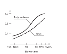
As in many other areas break-out frictionof elastomers is significantly higher than running friction. Apart from compound type and seal geometry, tendency to adhesion, deformation, the down-time and the surface finish play a role in increasing break-out friction. The longer the down-time, the more lubrica- tion is squeezed from between the seal and the running surface resulting in a non-lubricated vacuum. In this condition the level of starting friction approaches that for dry friction and is up to 10 times that found in running friction (Figs 6.18 and 6.17). For the same conditions, friction at high temperature (= low vis- cosity) is high because the lubricating film is often interrupted. 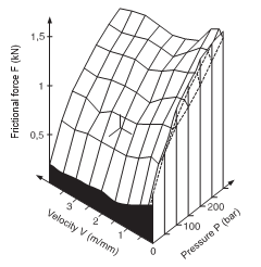
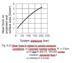
The most important factors can be seen in Fig 6.19. Here friction is shown as a function of pressure and velocity. Fig 6.19 is valid only for a specific seal in a particular application. For other seals and applications the interdependence varies. The stick-slip effect also is related to the friction at the sealing face. The friction, or better expressed the difference between break-out and running friction, plays an important role in evalua- tion and selection of a suitable elastomer. Break-out friction occurs when the three following conditions are present:
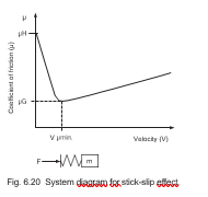
To assist in the explanation of the term stick-slip, please refer to Fig 6.20. To accelerate a mass m from zero to maximum veloc- ity, the break-out friction µH must be overcome by F1. The spring element is loaded with F1 and with increasing velocity the friction value µH reduces to µG and the force to F2 The potential energy stored in the spring accelerates the mass even further. When the stored energy is used, the mass is decelerated by the increasing friction in direction µH. This requires once again an increase in the force level of F1, and the procedure repeats again.
Running velocity is a product of seal friction, the piston mass and the load. Of all these factors, only friction can be influenced and makes for a better relationship between sealing surface finish, lubricating film and surface finish running very important. Cer- tain improvements can be made making the system stiffer, this means the smallest possible oil volume under pressure on the hydraulic side.
A radial oscillation of the piston will occur when the lubricat- ing film breaks down. Conversely oils with strong film building properties do not break down under the same working conditions using the same seals.
Pneumatic seal
In principle the same conditions apply here as for the hydraulic seal, except that the effects of certain extreme conditions are more serious. This is particularly the case when lubrication is poor, as found when lubricated air is not available. Lubricated air gives more or less the same results as in a hydraulic applica- tion. When lubricating grease is not continually replaced, it can even- tually be removed by a seal lip. The effectiveness of lubrication with grease depends on the thickness of the original film and the running velocity of the seal (Fig 6.21). The lower the velocity the thinner the lubricating film will become With an O-ring seal the loss of grease can lead to total break- down of the hydrodynamic lubricating film after only a few slow strokes. Breakdown of the lubricating film after long operation also results in contact between the seal and the metal surfaces. This makes the seal move in the mixed friction range and the increase in friction causes high wear. The lubricating film therefore must be protected by rounding of the seal wiper edges and complete wiping of grease from the running surface must be prevented. This action has little effect upon the starting friction but brings a noticeable improvement in running friction levels.
If slow pneumatic piston velocities are achieved throttling the pressurising air, the risk of high stick-slip increases. Stick-slip is effected directly negatively by long seal lips and sharp seal edges. An extremely rough or fine polished metallic running sur- face causes equally higher stick-slip.
Friction causes wear. However, friction can be anticipated and taken into consideration in the design stage. The wear rate how- ever is difficult to predict but directly governs the lifetime of an O-ring and the frequency of maintenance.
Today´s high precision machinery tends in most cases to elimi- nate hydrodynamic lubrication because of the increased wipe-off effect. This means the seal always functions in semidry condition and for this reason wear resistance depends on:
Wear in fluid solutions can be divided into four groups:
Scuff wear develops with metal-to-metal contact in the semidry condition where both materials tend to form mixed crystals. HPL oils help to prevent this contact because of their additives. These additives have no influence in rubber/steel or rubber/metal com- binations.
Fatigue wear becomes evident when particles are released from the metal structure and is usually the result of pulsating loads. Corrosion wear manifests itself in the form of rust and can nor- mally be reduced by suitable oil additives. Seals are not directly affected by the above types of wear. However, in dynamic appli- cations particularly these wear conditions can cause the seal to fail through abrasion.
Abrasive wear can affect both metallic and seal areas. Metals are abraded by hard compounds or by hard foreign matter in the medium. A rough metal surface normally is the cause of elas- tomer abrasion.
The seal user normally has no profound knowledge of seal wear characteristics. It is therefore recommended to consult the manufacturer about details of all extreme application conditions so that the correct seal can be offered.
In order to obtain a problem-free seal it is necessary to have stability with regard to the clearance gap to avoid possible ex- trusion. However, stability is difficult to achieve because the relevant parameters often work conversely.
The first consideration is the lubricating film in the clearance gap. To estimate friction, lifetime and leakage it is necessary to know the width of the gap and how it varies under working conditions. To keep friction as low as possible the lubricating film should be fairly substantial. This, however, can result in leakage because the “thick” film is wiped off the rod surface during the return stroke. In the other extreme a lacking lubricating film causes problems due to high friction. The effectiveness of a seal and friction therefore are inversely proportional.
Hardness together with the width and length of a clearance gap is very important. The hardness determines the elasticity of the seal and assures that the seal gives way to the lubricating film under pressure. The instantaneous viscosity of the fluid also plays an important role in resisting the wiping effect of the seal. It is still not known which factors influence the lubricating film and which mechanisms act in the clearance gap. A soft compound fa- vours a thicker film. Hard and soft compounds behave differently at high velocities, harder compounds help form a lubricating film whereas a soft compound will hinder this by strong adhesion to the running surface.
The lubricating film is very important but only one of the factors affecting seal friction. Other factors are, for example, the seal compound, seal shape, pressure, velocity, and changes in di- rection. Often many of these factors are difficult to measure or reproduce.
It is therefore understandable that seal manufacturers cannot give customers fixed figures regarding friction and wear for an individual seal. Information about seal lifetimes only can be made when all parameters affecting the seal are known and reproducible. General assumptions from a few tests are not acceptable because laboratory tests never can reproduce real working situations.
The elongation at break is the elongation measured at the mo- ment of rupture of a specimen under tensile load. The test is carried out to DIN 53 504. The test result – elongation at break – is a useful indication of suitability of a compound for seals which eventually must be stretched by a large percentage during assembly, e.g. stretching of small O-rings can cause difficulty in practical situations. The finished product, e.g. the O-ring, is much more sensitive to elon- gation than the specimen because of its special geometry.
Tensile strength is measured in N/mm2 and is the force per area necessary to tear up a standard specimen at a given rate of elon- gation. For the standard O-ring, 500 mm/minute is taken and for the S1 standard specimen. For standard specimens S2, S3 and S4, the value 200 mm/minute is taken. Tests comply with DIN 53 504. In practical terms, the results of these tests do not assist the user to select a compound because an assembled O-ring does not rely on its tensile strength in achieving a seal. As with elongation, tensile strength depends on the specimen geometry. O-rings and Parbak rings with small cross-sections give inferior results when compared with standard specimens.
Stress relaxation of elastomers is the reduction of stress in the deformed elastomer resulting from physical and chemical proc- esses. The reduction of stress is made evident, for example, by the gradual decrease of the inherent sealing force of o-rings over time. Like compression set, stress relaxation is dependent on the particular type of elastomer, mixture composition, processing parameters, deformation, material thickness, time, temperature and media influence.
A large number of test standards and test rigs are available to measure stress relaxation under laboratory conditions. The most common test standards are DIN 53537, ISO 3384 and ASTM D 6147. A distinction is made between continuous and discontinu- ous measurements. With continuous measurements the elastic force is continuously measured online, whereas with discontinu- ous measurements the test specimen must be removed from the deformation test rig to measure the elastic force.
Since the various test methods give clearly differing results, only those results measured under exactly the same conditions are comparable with each other. With regard to evaluating the performance capability of a seal the stress relaxation values are more conclusive than compression set, since with stress relaxa- tion the retained sealing force is measured, not the permanent set. Yet even the results of a stress relaxation measurement only allow a sound conclusion concerning the sealing performance in field application to be drawn if the respective application condi- tions are considered as well.
The testing of elasticity can also be carried out by rebound test- ing according to DIN 53 512. Rebound elasticity gives reference points from which the dynamic behaviour of compounds can be compared. In section 7.11 the relationship between temperature and rebound, hardness and compression set can be seen.
Elastomers lose their flexibility with increasing levels of radiation. Radiation is a medium which causes breaking down of the poly- mer chains which form the elastomer. The cross-linking process quickens under increasing radiation dosage, tensile strength and elongation at break decrease, hardness and modulus increase. The elastomer also becomes brittle. Conversely butyl rubber IIR becomes soft and sticky. In general terms elastomers have resistance to radiation levels of 1 M rad = 106 rad without losing their elastic properties. 1 M rad is a dosage level which normally would be reached after years of operation. At 10 M rad (= 107 rad) the physical proper- ties are effected. The change in compression set is certainly the most important property affected by increased radiation. The most suitable compound is EPDM. An elastomer normally is exposed to other media in addition to radiation, e.g. water, steam, oil, air and chemicals. These sec- ondary media often are of primary importance because extreme temperatures, e.g. +150°C in steam, may cause seal failure after very short time.

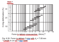
The force necessary to deform an O-ring cross-section by a given amount (in percent) is related to the compound modulus and O-ring geometry. Normally the user knows the compound hardness and the deformation in percent, the following diagrams (Fig. 6.25 to Fig. 6.29) show the relationship between hardness, deformation and cross-section.
The range of loads given in the diagrams refers to all elastomers. The forces required to deform elastomers during assembly can be estimated from the diagrams and the force imparted to the metal, aluminium or plastic gland faces also can be obtained.
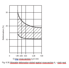
The minimum allowable deformation depends upon the type of application. A low deformation can lead to a 100% compression set in a very short time. When the deformation is too high it leads to a high compression set. In dynamic applications high deformation leads to increased fric- tional forces and higher temperatures. The characteristic curves shown in Fig: 6.30 to Fig. 6.32 take into account elongation, cross-section reduction and metal toler- ances for seals under normal conditions. In special cases minimum deformation also is effected by over- stretched rings, influence of temperature, breathing of cylinders, eccentricity, etc.
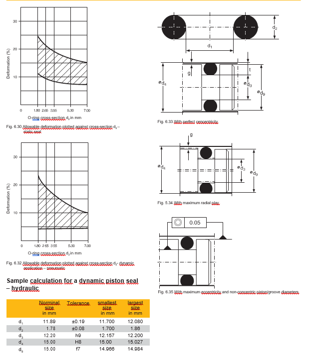
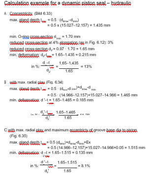
The example shows the effect which O-ring elongation and ec-
centricity of machine elements can have on section deformation and O-ring sealing capability.
O-rings contact a wide range of media. All media, gas, vapour or fluid tend to be absorbed by the rubber and can affect the material in various ways:
Changes due to physical effects can be described by two pro- cedures that can act concurrently:
When a) is greater than b), the net result is swelling; when b) is greater than a), shrinkage occurs.
The amount of volume change depends on the type of medium, components of the elastomer, temperature, geometrical shape (material thickness), and on deformation of the O-ring. When compressed an O-ring swells by up to 50% less than in the free state. Laboratory tests for compatibility are made on O-rings in the free state.
The maximum degree to which individual cured compounds swell and reach equilibrium depends on the elastomer type.
Changes in volume, both positive and negative, result in chang- es of the physical elastomer properties, e.g. hardness, elasticity, tensile strength, elongation at break, and low temperature be- haviour. All changes in physical properties can, according to their intensity, lead to degrading of the elastomer and even to com-plete functional failure. For additional information regarding the compatibility with mineral oil, see Section 6.7. ECI – Elastomer Compatibility Index.
Changes in an elastomer caused by chemical attack are ir- reversible. Cracking of cross-link sites or the formation of new additional sites lead to complete deterioration of all properties necessary to prevent leakage. Even the smallest chemical change in an elastomer can lead to a serious loss of physical properties (e.g. embrittlement). The compatibility of elastomers with a medium is extremely important. The degree of compat- ibility between compound and medium thus should be known be- 2 max fore any sealing compound is specified to avoid system failure. The suitability or non-suitability of an elastomer in a particular medium can be taken from our Medium Compatibility Table, catalogue no. 5703 E.
Tear resistance (N/mm) is defined as the maximum force which causes a nick in a defined specimen to propagate into a tear. The test is carried out to DIN ISO 34-1 on a straight or angled specimen. The tear resistance is a measure