Although made responsible for many disasters, O-rings seldom are the cause. More frequently the people responsible for de- sign, assembly or maintenance have made an error.
Optimum lifetime and reliability can be achieved only by select- ing the proper O-ring compound and having full understanding of the various factors that influence the function of a seal. The following descriptions characterize the most frequent types of O-ring failures, stating their causes and how these can be cor- rected to prevent future failure.
Since seals are used in a wide range of different applications, the resulting requirements may differ as well. Typical requirements include:
Owing to the diversity of applications and the fact that the relatively simple geometry is specified, chemical and physical properties are particularly critical factors. This is where our field application consulting support comes in to help identify the mate- rial best suiting the user’s needs from the wide range of synthetic rubber compounds available or to select the one that offers a viable compromise for the various requirements. Usually, defects are evident directly on the o-ring. This enables corrections to be made, such as changing the compound.
The pressure ranges given by the extrusion diagram (Fig 8.6) have been obtained by experiment and give important hints as to when it is necessary to use backup rings. See figures 9.1, 9.2, 9.3 and 9.4.
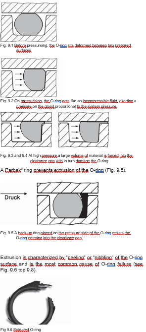
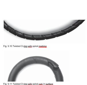
Extrusion is caused by:
The main reason for this failure is known. The production depart- ment needs larger tolerances for more economic manufacture. The other reason which goes largely unnoticed is the tendency of lids, flanges or cylinders to flex and that of bolts to stretch under load. Extrusion is caused by the O-ring cross-section being forced into the clearance gap (see Fig 9.4). This type of failure is exagger- ated in dynamic applications where material is clamped in the clearance gap and sheared. Machine elements which “breath” or operate under high or pulsating pressures are particularly susceptible. The resistance to extrusion of materials can be optimally com- pared using modulus values at 100% elongation. If no modulus values be available, hardness in IRHD can be usefully compared and used to select the appropriate maximum pressure level. Original physical properties are a function of temperature. An ex- ample of this would be silicone (VMQ) and fluorosilicone (FVMQ) elastomers. Both show reduced tensile strength values at higher temperatures. With such compounds the clearance gap should be reduced by 50%.
Extrusion failure is caused by the following situations:
Corrective action:
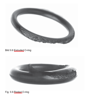
The range of pressures and/or clearance gaps which require the use of Parbak® back-up rings can be seen in Fig 8.6. In recipro- cating applications two Parbaks® are necessary.
Compression set, the partial or total loss of an elastomer´s elas- tic memory is the most common failure. It is characterised by double-sided flattening of an O-ring (radial or axial, to applica- tion) and can be clearly seen after disassembly. The problem is caused solely by selection of the wrong com- pound. Elasticity of a seal depends not only on the rubber recipe but also on working temperature, type and length of deforma- tion and on ageing caused by a medium (e.g. air, steam, acid, petroleum). Compression set can be described simply as the loss of cross- link sites between molecule chains or as the creation of new sites (brought about through temperature changes). The compression set clearly visible at temperatures below freez- ing generally is reversible. At higher temperatures the elasticity returns and the sealing force acts again.
The causes of high temperature compression set and loss in sealing effect are connected and can be described as follows:
Failures of this kind can be avoided by changes as follows:
Another O-ring failure is caused by dry running. The O-ring sur- face is characterized by a spiral mark which eventually develops into a deep cut causing failure (see Fig 9.10 and 9.11).
The failure occurs as follows:
In a static application the O-ring becomes twisted during as- sembly. This is mainly due to the unsuitable relationship be- tween large inner diameter and small cross-section diameter
The causes of failure are:
This failure can be avoided as follows:
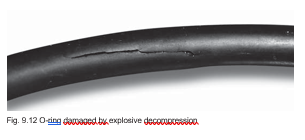
Since all elastomers are permeable, pressurised gases will per- meate the sealing material. The higher the pressure the more gas is pressed into the seal. If the ambient pressure around the seal is reduced quickly, the gas inside the seal will expand and escape, or there will be a formation of blisters. Some of these blisters may burst and damage the surface. This process is called explosive decompression. A seal’s susceptibility to dam- age depends, for example, on pressure, decompression time, the type of gas, type of compound and the o-ring cross-section. Damage rarely occurs below 30 bar. Generally, CO2 gas is more likely to lead to blistering and surface destruction than nitrogen, yet any compressed gas may cause this type of surface destruc- tion after sudden decompression (figure 9.12)
Whenever there is any indication of such damage the mere use of o-rings with a smaller cross-section may remedy this situation because this reduces the free surface. Normally, the tendency to blister is reduced as hardness increases. Compounds with very high gas permeability rates – such as silicone compounds – will release the gas inside more quickly in case of rapid decompression than those with very low gas per- meability rates, such as butyl compounds. The following compounds show good resistance to explosive decompression: N 552-90, S 604-70
This problem can be solved in the following ways:
The following Parker compounds show good resistance to explo- sive decompression: N 552-90, S 604-70.
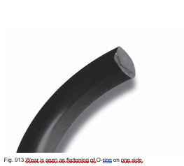
Wear is possibly the most understandable form of O-ring failure in reciprocating, rotating and oscillating machine parts. In under- standing this type of failure it is important to note that friction is proportional to deformation and that applied pressure and wear are proportional to friction, and further that the temperature in- crease of the seal is proportional to friction. The single parameters must be considered along with the me- dium to arrive at the optimum compromise. In static applications damage through wear is caused by pulsating pressure which causes the O-ring to abrade on relatively rough surfaces or the edges of the glands.
Even if all the above hints and rules are observed failure can still occur. Many of these failures can be traced back to assembly stage. O-rings are highly sensitive precision products and should be treated with the greatest respect. They must not be mishan- dled. Only assembly carried out with great care will pay a good dividend in the form of a trouble-free machine and a satisfied customer. The alternative is a piece of equipment which could fail on com- missioning or shortly thereafter.
Assembly failures can be caused easily by:
Assembly failures can be avoided by:
Damage to O-rings can be caused by compounding of the above causes. On the failure of an O-ring all the above causes should be checked. Further information can be taken from section 10. Assembly hints.